To replace the many pieces of the shop project which were ravaged by the elements and pilfered over time, I had to quickly develop a careful eye toward Bantam parts. I learned early on that it is very easy to waste money and time on incorrect parts. The series on the build for the Sportsman is not only an advertisement for our locating and parts services, but also serves as a primer to help you with your project. If you don’t have a project yet, hopefully this will inspire you to take one on and arm you with information necessary to avoid common pitfalls.
Considering that many of the production changes of the American Austin and Bantam cars were more evolutionary than revolutionary, you may not have expected there to be a large divergence between the underpinnings of each car. While the chassis of each sort of car should fit under the other, they are all very distinct and each have their own eccentricities of which you need to be mindful.
American Austins, of all shapes and sizes, used one style of frame. The Austin frame was essentially a v-shaped unit, with no connection at the rear end of the car. If you’re building an American Austin, your chassis selection is pretty simple. If you are hoping to underpin your American Austin with a Bantam Chassis for added support and driveline flexibility, you should continue reading.

An American Austin chassis fitted with some Bantam parts. Note the parallel central crossmembers which are joined by a perpendicular piece with numerous holes along its length. Also, note the terminal ends of the chassis, they are straight once they get to the center-line of the rear axle. They are also not connected by anything other than the rear bumper on some models and a thin bracket and bumper on others.
When production resumed as American Bantam, the new cars found themselves equipped with a new frame. This new frame looked identical to the Austin up until the forward transverse crossmember. A pair of members now extended from that forward central crossmember to two partial members extending out of the frame just before its upward flare near the rear wheels. This pair of members formed a V shape and allowed Bantam to switch from a torque tube based drive line to a more modern drive shaft.

At the rear of the chassis, Bantam used at least three different styles of rear crossmembers which were used for different cars. Roadsters and coupes had the two rear frame rails unified by a length of thin c-channel in earlier years. In the final year of production, that thin c channel was replaced with a heavier c channel with a shallower c-shape. Bantam commercial cars utilized a tubular rear crossmember which also served as a spare tire carrier. This rear member consisted of two tubes connected by a flat piece of steel. Bantam four passenger convertibles utilized the larger tubular member from the commercial frames, but forwent the smaller tube, prohibiting the crossmember from serving as a spare tire mount so as to clear the unique floor for accommodating rear passengers.
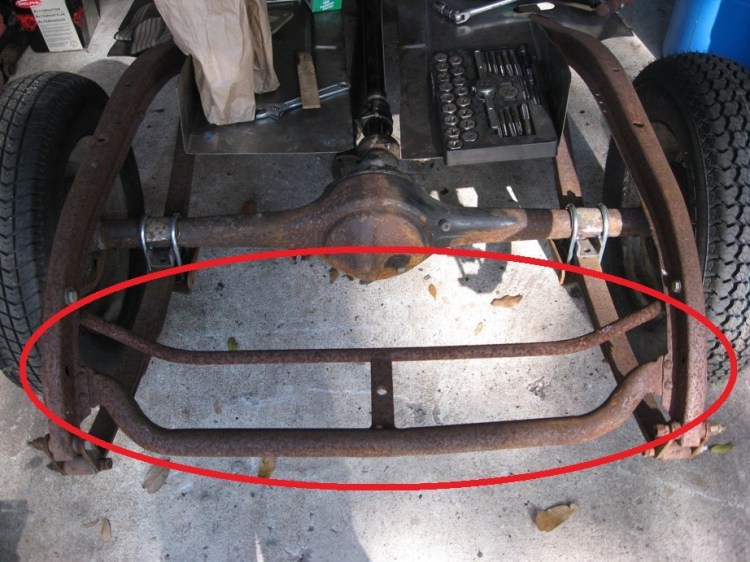
Here is a photo of a Commercial Style rear cross member. For a four passenger convertible, the chassis only utilized the larger tubular member and deleted the reset of the components.
For series 65 Bantams equipped with the three main engine, these cars featured a new drive train mounting method which also included a new means of attaching the radius rods. As such 1940 frames have cast brackets riveted into the corners created by the full transverse crossmember and the frame rails which are absent on all earlier models. The 1940 also has a ball style socket for the radius rods to couple onto providing for a greater freedom of motion for the rods as compared with the earlier style mount.


1940 vehicles equipped with hydraulic shock absorbers, primarily passenger cars, had a pair of cast brackets riveted to the frame in the rear above where the axle would ride and had a pair of bent steel front mounts riveted where the forged front cross member meets the frame rails. These should not be mounted on other frames, unless the vehicle was equipped with dealer added shock abosorbers (I’m still hoping to learn more about cars with added shocks).


1940 Bantams also had an extra pair of floor supports located on the V shaped frame members. These brackets were not available previously.

The next difference between a 1940 frame and earlier style frames is the manner in which the central transverse crossmember is clearanced for the exhaust system. For a 1940 Bantam with a three main bearing engine, your chassis should look like the photo on the left. For any other Bantam, your chassis should merely have a hole cut through the crossmember. This hole will likely be larger than the hole on the driver side of the chassis.


The final difference between the frames revolves around the parking brake assembly attached to the chassis. The earliest Bantams featured a hand brake on the passenger side of the transmission which protrudes from the floor and is pulled back to engage the brake. This assembly requires a mounting bracket attached to the transverse crossmember. It also requires that the transverse brake actuation bar has a pinned member which can be actuated by the pulling of the lever. This pinned member will be located the passenger side of the bar, between the center line of the frame and the frame rail. I will have to find some photos of this set up and add them here later.
In 1939, Bantam introduced a new brake assembly which was also floor mounted, but was located under the drivers legs and pulled up. This assembly featured a bracket which would support the floor riveted to one of the members making up the v shaped crossmember. This set up also included a cast or forged lever through which the brake actuation bar passes at one end and can be moved by the raising and lowering of the brake handle. The lever rides free on the actuation bar and pushes against a pinned member when the brake is engaged.


The final variation arrived at some point for 1940 cars. At this point, the brake bar was endowed with a second pinned lever identical to the standard pinned lever which the brake pedal actuated. These levers should be fairly close to each other. This added lever was actuated by an adjustable link attached to a pivoting bar pinned to the chassis. The pivoting bar was moved by a brake cable which ran into the passenger compartment to a parking brake handle mounted to the underside of the dashboard. To limit unwanted motion, the cable was fixed at one end to in cabin assembly and to the chassis by a brake cable retention bracket similar to those used elsewhere of the chassis.

As you can see, Bantam chassis are not very interchangeable despite a similar appearance. You can take one chassis and likely modify it to accommodate your required functionality, but please be aware that such a procedure is very time consuming. There are a lot of bare frames out there waiting for love, you are likely best off taking a bit of time to scour the available parts for just the chassis you need rather than modifying an original chassis. As you follow along with this project, you’ll see that I have learned this lesson the hard way.
If you are seeking a four passenger or commercial chassis, you may need to consider modifying a standard chassis for the correct model Bantam and acquiring a tubular rear cross member assembly. As a warning, original tubular rear cross members are difficult to find in decent shape, however we can now supply you with fantastic reproductions.
